SubSLAM® for riser verticality measurements
Client: Anonymous
Location: United Kingdom
Solution: SubSLAM® X2
Industry: Oil & Gas
Rovco powered by Vaarst technology, was tasked by a leading Oil & Gas major operator to inspect the relative position of vertical conductors, located inside a jacket structure from a depth of approximately 80m to seabed.
The client required up to date information on the verticality of the conductors and was interested in innovative solutions that could be deployed from vessels already available on-site, avoiding the deployment of a dedicated vessel, which would have extended the cost and time profile of the operation.
Use of imaging sonar technology would have required a dedicated vessel with a full USBL and INS positioning spread. The resolution of an imaging sonar would have been in the region of 5+ cm in the best case, which still would not have satisfied client’s requirements.
Use of acoustics measurement sensors like gyro-compatts was not feasible given the length of the connectors. It would have also still required a dedicated vessel to establish a positioning environment for the sensors.
The inspection was successful in its aims to:
-
- Collect data in a reduced time window, with overall data collection consisting of 13 hours over 3 dives.
- Deliver the survey using assets already available on-site.
- Provide accurate information on the relative spacing of the structure’s conductors where they enter the seabed and to the jacket legs at two depths (described as Depth ‘A’ and ‘Seabed’).
- Provide accurate information on the relative spacing of the structure’s conductors where they depart the guide funnels and to the jacket legs at Depth ‘A’.
- Provide analysis of the verticality of each of the conductors from Depth ‘A’ to ‘Seabed’.
- Obtain an accurate 3D point cloud, tied into the specified coordinate reference frame.

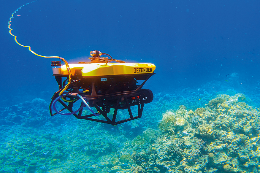
To achieve the above, Rovco utilised a Seaeye Cougar XTC, fitted with Vaarst’s SubSLAM® X1 live 3D reconstruction system, launched from a jack-up barge adjacent to the well-head platform. This facilitated mapping of the conductors during a standard general visual inspection scope of work.
Project Methodology
Vaarst’s SubSLAM® System is a real-time 3D imaging system based on the latest innovations and advanced internal research in Computer Vision and AI. By utilising a calibrated pair of stereo 4K sensors, true scale and true colour digital reconstructions of assets can be produced live. The 3D reconstruction happens at the same time as a visual Inspection, giving the ability to carry out two tasks at once and offering the video dataset as a backup to the 3D survey.
Secondly, due to the stereo cameras, the output of the 3D model is perfectly scaled to the real-world, without the need for rulers, scales or any physical measurements that can introduce additional sources of error.
The point cloud and imagery collected using SubSLAM® can be used in three different ways, according to the project specifications:
- The live 3D model provides an indication of data coverage and allows coarse measurements to be taken.
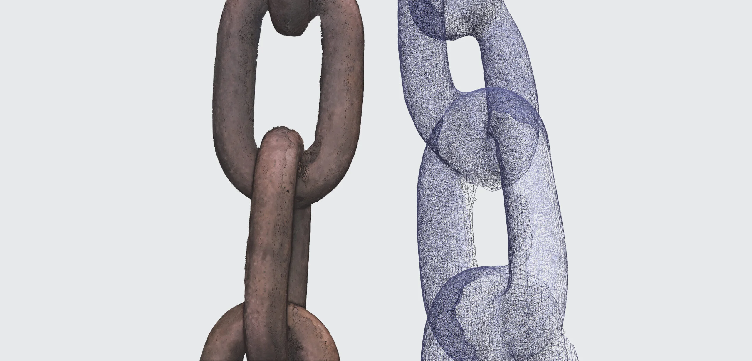
- The same data can be post-processed to produce a 3D model suitable for measurements with sub-centimetre tolerances.
- Finally, to achieve millimetric accuracy measurements, the contractor post-processes the data using photogrammetry techniques. Photogrammetric models are produced with access to all image data from the outset, as opposed to the streaming data model necessary for live 3D modelling.
By using the global collection of images and significant compute and optimization resources, photogrammetry provides a highly accurate dense 3D reconstruction. The same calibration that enables live 3D reconstruction can be used to scale a photogrammetric model.

In order to translate the data points from model coordinates to absolute coordinates, the following methodology was adopted, starting from the client-provided real-world position for centre point of platform and real-world azimuth of the platform:
Depth A
- Model centre positions of 3 platform legs calculated using the same methodology as conductor centres
- Model “platform centre” calculated from leg positions
- Model azimuth calculated using the angle between legs
- Model rotated and transposed to match real-world data
Seabed
- Model centre positions of 2 platform legs calculated using the same methodology as conductor centres
- Model azimuth calculated using cross member running between legs
- Real-world positions for legs calculated from .dxf files supplied by the client
- Model rotated and transposed to match real-world data
Summary of Project Results
All legs, members, risers, conductors, guides, and seabed were scanned, with data being recorded at all times during the inspection to incorporate sufficient redundancy.
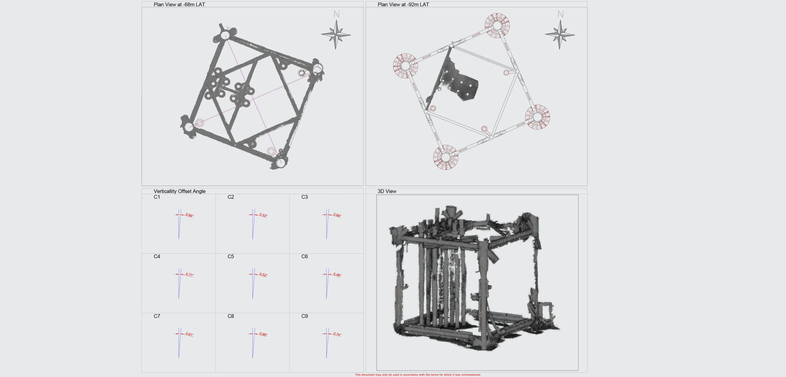
A 3D point cloud reconstruction of the section of the jacket structure from Depth ‘A’ to ‘Seabed’ (Figure 2) was created. This was then displayed in two sections of point clouds at Depth ’A’ (Figure 3) and ‘Seabed’ (Figure 2) to enable easier identification of assets and to perform verticality measurements.


Conclusion
Using Vaarst’s unique SubSLAM® Technology, a precise 3D Point cloud of the Jacket was created, from which a variety of accurate measurements were taken. These enabled the verticality of the risers to be measured, showing all the risers to a vertical offset angle of less than 1o.
SubSLAM® was instrumental in supporting this task where traditional acoustic systems were not deemed suitable, demonstrating the technology’s capability to deliver millimetre-accurate results in a shorter time window.
Accurate data in line with client’s tolerances and requirements were generated, SubSLAM®’s flexible approach allowed for several cost-saving measures:
- SubSLAM® can be easily deployed on a Seaeye Cougar XTC or any observation class vehicle, from infrastructure already available on-site, no need to mobilise a dedicated vessel.
- SubSLAM® can create millimetric-accurate datasets without the need for additional positioning systems, reducing operational days. The system can start recording almost immediately, as calibration operations can be carried out in minutes rather than days.
- SubSLAM®’s capability to auto-scale expands the capabilities for photogrammetry post-processing, further reducing risks and margins of error.
- Provide accurate information on the relative spacing of the structure’s conductors where they enter the seabed and to the jacket legs at two depths (described as Depth ‘A’ and ‘Seabed’).
- Provide accurate information on the relative spacing of the structure’s conductors where they depart the guide funnels and to the jacket legs at Depth ‘A’.
- Provide analysis of the verticality of each of the conductors from Depth ‘A’ to ‘Seabed’.
- Obtain an accurate 3D point cloud, tied into the specified coordinate reference frame.
SubSLAM® has since launched an improved and more robust system with SubSLAM® X2, which boosts processing power over the X1 version used on this project. Replaying the same dataset collected on this project with the most recent and improved software, Vaarst’s technology was capable of reconstructing the full length of the risers (24m) in one single pass.

This recent innovation would further reduce operational hours on metrology scopes.
Similar stories

We are proud to announce our collaboration with Red Sea Global (RSG), a visionary developer spearheading regenerative tourism projects worldwide.…

